About Us Products Touch Vedio News Solutions FAQ Technologies Aftersale-Service Download Contact Us
Touch Screen Tech.
Capacitive Touch - New Arrial
Multi Dualtouch Tech.
Multi Touch Overlay Technology
Multitouch Splicing Wall
Touch Foil Film Tech.
Touch Whiteboard Tech.
Touch Frame Android MINI PC

Touch Screen Tech. 

4Wire Resistive Touch Screen Working Principle:

The 4 Wire Resistive Touch Screen is a two-layer structure,
1. ITO glass substrate with one side uniform resistive ITO coating.
2. A very thick polyester ITO film which tightly suspended over the top of the ITO glass substrate. This PET film has a hard, durable coating on the outer side, on the inner side with ITO coating.
3. ITO glass and the ITO film are separated by printed small, transparent insulation spacer dots.
When the screen is touched, it pushes the ITO film to have electrical contact with ITO glass (both on the ITO coating side). It produces a voltage which is the analog representation of the position touched.

 In 4 Wire Resistive, the ITO glass (glass substrate) is set as Y-axis and ITO film as X-axis. The microprocessor of the controller applies +5V voltage to XL (X-axis left) on the ITO film, and the voltage uniformly decreases to XR(X-axis right) in zero voltage. In the same process, the microprocessor applies +5V voltage to YU (Y-axis up) on the ITO glass, and the voltage uniformly decreases to YD (Y-axis down) in zero voltage. When the screen is not touched, the controller detects the voltage on ITO glass / ITO film as zero voltage.

 When the screen is touched, the voltage on the ITO film proportional to the X-axis (horizontal) position of the touchpoint appears on the ITO glass. Next, the voltage on the ITO glass proportional to the Y-axis (vertical) position of the touchpoint appears on the ITO film. These two voltages appearing on the ITO film and ITO glass are digitized by the A/D converter and then transmitted to the host.

 The controller will receive all data to get the touched position according to the established calculating mode to figure out the exact X and Y coordinates


Advantages

  • Can be activated with any device
  • Low-cost solution
  • Low power consumption
  • Disadvantages
  • Less durability compared to other technologies
  • Less transmittance and overall optical quality
  • Requires periodic recalibration


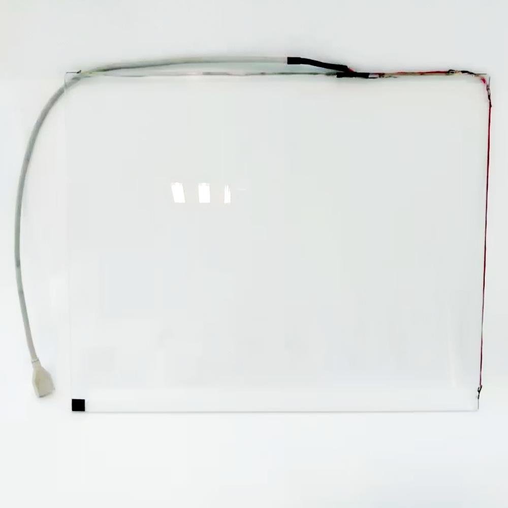
5 Wire Resistive Touch Screen Working Principle:

The 5 Wire Resistive Touch Screen is a two-layer structure,
1.ITO glass substrate with one side uniform resistive ITO coating.
2. A very thick polyester ITO film is tightly suspended over the top of the ITO glass substrate. This ITO film has a hard, durable coating on the outer side, on an inner side with ITO coating.
3. The ITO glass and the ITO film are separated by printed small, transparent insulation spacer dots.

When the screen is touched, it pushes the ITO film to have electrical contact with ITO glass (both on the ITO coating side). It then produces a voltage which is the analog representation of the position touched.

 The 5 wire touch screen controller is always ready for a touch, and the resistive layer of the touch screen is biased at +5V through 4 drive lines on the glass (ITO coating side) and the ITO film is grounded through a high resistance. When there is no touch on the screen, the voltage is zero on the ITO film. The voltage level of the ITO film is analog - to - digital converter (A/D converter) and monitored by the microprocessor on the controller.

   When the screen is touched, the microprocessor detects the voltage rise in the ITO film and begins to convert the coordinates. The microprocessor places the X drive voltage by applying +5V voltage to pins H, X and grounding pins Y and L. The analog voltage is proportional to the X position (horizontal) of the touchpoint and appears on the ITO film at pin S of the touch screen tail's connector. This voltage is digitized by the A/D converter and transmitted to the computer.  

 In the same process, the microprocessor places the Y drive voltage by the same +5V to pins H, Y and ground pins X and L. The analog voltage is proportional to the Y position (vertical) of touchpoint and appears on the ITO film at pin S of the touch screen tail's connector. The signal is converted and processed the same as for the X position.

 The controller will receive all data to calculate the touched position according to pre-established modes for the exact X and Y coordinates.

Advantages

  • Can be activated with any device
  • Low-cost solution
  • Low power consumption
  • Disadvantages
  • Less durability compared to other technologies
  • Less transmittance and overall optical quality
  • Requires periodic recalibration

Applications:

  • 5 Wire Resistive touch screen is with the most extensive applications.
  • Point-of-Sale uses convenience store, movie theater, lottery terminal, fast food, etc.
  • Industrial uses Automated testing, automation equipment, man。machine interface, etc.
  • Medical uses medical instruments, research equipment, and patient monitoring systems.
  • Transportation uses: Inner vehicle control panel.


Infrared Touch Screen Working Principle:

Infrared Touch Screen is a touch frame that is usually installed in front of the display screen. The frame is integrated with a printed circuit board which contains a line of IR-LEDs and photo transistors hidden behind the bezel of the touch frame. Each of IR-LEDs and photo transistors is set on the opposite sides to create a grid of invisible infrared light. The bezel shields the parts from the operation environment while allowing the IR beams to pass through.

 The Infrared Touch Screen controller sequentially pulses LEDs to create a grid of IR light beams. When a user touches the screen, enters the grid by a stylus that can interrupt the IR light beams, the photo transistors from X and Y axes detect the IR light beams that have been interrupted and transmit exact signals that identify the X and Y axes coordinates to the host.


Advantages

  • The highest quality of the underlying image
  • Very high transmittance (no conductive layers, only glass between image
  • Excellent anti-glare, with use of chemically etched glass
  • Can be activated with almost any device
  • Higher accuracy than other technologies<br>
  • Very high durability and reliability
  • One time factory calibration
  • Can be sealed
  • No wear mechanism

Disadvantages

  • Surface obstructions can cause a false touch

Applications:
 
  • Indoor/outdoor kiosks
  • Ticketing machines
  • Medical instrumentation
  • Process control systems
  • ATMs
  • Hospital operating rooms
  • Commercial transportation
  • Large plasma displays


SAW Touch Screen working principle:

SAW Touch Screen parts include: Sensor / Control Card / Cables. There are 4 transducers attached to the beveled edges of the glass for both X and Y axes
( 2 for transmitting and 2 for receiving).

The control card sends electrical signals to transmitting transducers of both X and Y axes. The transducers convert these electrical signals from the control card into ultrasonic waves sent to the array of reflectors on the glass surface, and the acoustic waves are directed across to the front surface of the glass by the array of reflectors (the degree of the array of reflectors depends on the updating design). The opposite reflectors will gather and direct waves to the receiving transducers which will convert the waves into the electrical signals.

 When a user touches the screen, the touchpoint coordinate is calculated by the control card comparing the received average amplitude of vibration of the acoustic wave signals and reference average waveform acquired when the touchscreen is in an untouched condition. The controller is capable of detecting the stay time of dirt, dust, water drops, scratches, and other contaminants on the screen and then ignores them. If the contamination is removed, the controller relearns the original reference average waveform.

Advantages

  • Very high transmittance
  • Very high durability

Disadvantages

  • Cannot be sealed
  • Requires “soft” input device
  • Surface obstructions can cause a false touch
     

Public access Application

  • Point-of-information kiosks
  • Gaming, lottery, and amusement
  • Vending and ticket sales
  • Public payphones
  • Multimedia marketing
  • Banking / financial transactions


Powered by DIYTrade.com
HomeContact UsSitemap